Well did you check the GCode? #1 Compute Start Radius (JK distance) #2 Find the Arc Center (Prev YZ then add JK) #3 Compute End Radius (Arc Center to Final YZ) #4 Compare
#5 show your work :}
TK
| Group: DynoMotion |
Message: 8650 |
From: eric_kato_sanders |
Date: 11/15/2013 |
| Subject: Re: Found a GCodeInterpreter.dll bug |
Hi Tom, I'll give that a shot. I never bothered to learn how to interpret the arc commands. I just did some reading and I think I have a handle on it.
Eric
---In DynoMotion@yahoogroups.com, <tk@...> wrote:
Well did you check the GCode? #1 Compute Start Radius (JK distance) #2 Find the Arc Center (Prev YZ then add JK) #3 Compute End Radius (Arc Center to Final YZ) #4 Compare
#5 show your work :}
TK
| Group: DynoMotion |
Message: 8651 |
From: eric_kato_sanders |
Date: 11/15/2013 |
| Subject: Re: Found a GCodeInterpreter.dll bug |
One additional question just so I understand how this works. The offending line is N3110 which describes the ending position. The starting position is from the previous line N3090 correct, so when I break it down, I see this:
starting position X-1.37418 Y-2.36992 Z-.150000
ending position X-1.34133 Y-2.33222 Z-0.10000 J0.00000 K0.05000
My question is the G19 sets our plane to YZ. In Mach, I see a curved line that extends up in the Z direction along the Y plane, but is rotated along the Z axis about the starting point such that ending x value is -1.34133. In other words, the arc is rotated about the starting point such that the end point is shifted in the X direction correct. Is my interpretation of how this works correct? So to calculated this, could I mathematically rotate the curve back onto the YZ plane, giving me a new Y coordinate, and work with that number to see if it ends up at the starting position defined by the previous G Code line?
---In DynoMotion@yahoogroups.com, <tk@...> wrote:
Well did you check the GCode? #1 Compute Start Radius (JK distance) #2 Find the Arc Center (Prev YZ then add JK) #3 Compute End Radius (Arc Center to Final YZ) #4 Compare
#5 show your work :}
TK
| Group: DynoMotion |
Message: 8652 |
From: eric_kato_sanders |
Date: 11/15/2013 |
| Subject: Re: Found a GCodeInterpreter.dll bug |
Tom, I'm going to work through this so you can see if my logic is wrong... Looking from above, the arc looks like this: / Referencing the graphic line above, the arc starts at the bottom, and sweeps upwards to the right. The amount it sweeps to the right is the difference between the starting and ending X positions defined in the G Code. In effect, the arc is along the YZ plane and is rotated clockwise about starting point along the Z axis. We have: starting position X-1.37418 Y-2.36992 Z-.150000 ending position X-1.34133 Y-2.33222 Z-0.10000 J0.00000 K0.05000 If the arc were not rotated, the ending Y position would be: YStart + .05 = -2.36992 + .05= -2.31992 If you now rotate the line about the bottom point such that the top is shifted by the amount indicated by the starting and ending X postitions, you will arrive at the final calculated Y position that should be within tolerance of the G code ending positions. xDiff=-1.34133-(-+1.37418) = 0.03285 < we want to rotate the line such that the ending point shifts over this is the amount Using trig, ater rotation, the distance from the starting Y to the ending yDist = sqrt(.05^5-.03285^2)=0.03769 So the calculated new Y postion should be YStart + yDist = -2.3322254712192870091053106455098 This agrees with what the G code ending Y position should be.within .00005" Eric ---In dynomotion@yahoogroups.com, <eric@...> wrote:
One additional question just so I understand how this works. The offending line is N3110 which describes the ending position. The starting position is from the previous line N3090 correct, so when I break it down, I see this:
starting position X-1.37418 Y-2.36992 Z-.150000
ending position X-1.34133 Y-2.33222 Z-0.10000 J0.00000 K0.05000
My question is the G19 sets our plane to YZ. In Mach, I see a curved line that extends up in the Z direction along the Y plane, but is rotated along the Z axis about the starting point such that ending x value is -1.34133. In other words, the arc is rotated about the starting point such that the end point is shifted in the X direction correct. Is my interpretation of how this works correct? So to calculated this, could I mathematically rotate the curve back onto the YZ plane, giving me a new Y coordinate, and work with that number to see if it ends up at the starting position defined by the previous G Code line?
---In DynoMotion@yahoogroups.com, <tk@...> wrote:
Well did you check the GCode? #1 Compute Start Radius (JK distance) #2 Find the Arc Center (Prev YZ then add JK) #3 Compute End Radius (Arc Center to Final YZ) #4 Compare
#5 show your work :}
TK
| Group: DynoMotion |
Message: 8656 |
From: Tom Kerekes |
Date: 11/15/2013 |
| Subject: Re: Found a GCodeInterpreter.dll bug |
Hi Eric, I don't really follow much of what you said. But I think you are over complicating things. The actual path forms a helix which is simply constant motion in the X axis as YZ do an Arc. For the purposes of this issue you can ignore the X motion. Just treat it as a simple arc in YZ. As a test you might remove the x motion from the GCode and see if you still get the error (you should). Also the K offset to center applies to the Z coordinate not the Y as I think you were doing.
Regards TK
| Group: DynoMotion |
Message: 8658 |
From: eric_kato_sanders |
Date: 11/16/2013 |
| Subject: Re: Found a GCodeInterpreter.dll bug |
> The actual path forms a helix which is simply constant motion in the X axis as YZ do an Arc. Things just clicked. In other words, the offset of the endpoint in the x direction is due to a simply translation in the x direction while the arc is formed in the YZ plane. What I calculated was result of taking an arc on the YZ plane and rotating is about the starting point in the Z axis. What I thought was being produced is a true arc. What is actually being produced is a helix.
What is strange is the CAM software is basing it's output on a true rotated arc, not a helix, (that's why my end point calculations matched their end point).
Given a helix, the end point should simply be the starting y point plus the arc radius since the arc is 90 degrees. the -2.36992 + .05 = -2.31992. The error now is -2.31992-2.33222 = .0123 which matches what the GCodeInterpreter.dll said it was.
It appears that MACH3 is VERY liberal with it's tolerences. Thanks for your time Tom.
---In dynomotion@yahoogroups.com, <eric@...> wrote:
Here is a small code snipped that runs fine in Mach, but errors out in KMotionCNC.
It
produces the "Radius to end of arc differs from start radius to start"
error message on line N3110. The code was generated for a .125 end
mill.
Looking at the GCodeInterpeter file rs274ngc.cpp, line 835, I
added a pop up message to display the error that is being compared to
the tolerance variable. Most all the arc errors are to the order of the
sixth decimal place. The offending line has a whopping computed error
of .0123.
A notation in the source code says that it will also catch
arc moves too small for the cutter diameter. Could the problem be that
the error checking isn't taking into account the G19 which puts the arc
in the YZ plane? Since the move in question is actually a 90 degree
.05" radius Z arc move up and away the cutter diameter shouldn't play a
role in the error detection as it would in the XY plane.
%
N0010 G00 G49 G17 G80 G90
N0020 G20
N2990 X-1.31146 Y-2.26179 Z-0.15000
N3000 G17
N3050 G01 X-1.37418 Y-2.36992
N3060 G03X-0.72295Y-2.64239I1.37328J2.36778
N3070 G02X-1.04857Y-1.81635I0.72384J0.76253
N3080 X-1.92684Y-1.94713I-0.57950J0.87722
N3090 G03X-1.37418Y-2.36992I1.92594J1.94499
N3100 G19
N3110 X-1.34133Y-2.33222Z-0.10000J0.00000K0.05000 F33.0
N3120 G01 Z-0.07500 F33.0
N8390 M5 M9 G49
N8400 M30
%
|
|
| Group: DynoMotion |
Message: 8659 |
From: eric_kato_sanders |
Date: 11/16/2013 |
| Subject: Re: Found a GCodeInterpreter.dll bug |
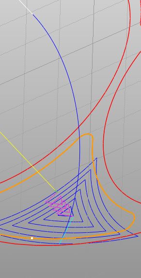
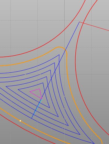
Tom, The arc in question is a cutter exit arc, where after the cut, the cutter sweeps up and away from the part. I changed the exit arc to 1" radius to make it easier to see. From the top view, it is a straight line, so it is definitely not a helix. So the question becomes, what *should* the G code look like for a true arc in the Z direction that is at an angle, (i.e. rotated about the Z axis). Two snippets are attached. One looking from top view and one angled view. By the way, at 1" Mach complains about it as well.
Eric
---In dynomotion@yahoogroups.com, <eric@...> wrote:
Here is a small code snipped that runs fine in Mach, but errors out in KMotionCNC.
It
produces the "Radius to end of arc differs from start radius to start"
error message on line N3110. The code was generated for a .125 end
mill.
Looking at the GCodeInterpeter file rs274ngc.cpp, line 835, I
added a pop up message to display the error that is being compared to
the tolerance variable. Most all the arc errors are to the order of the
sixth decimal place. The offending line has a whopping computed error
of .0123.
A notation in the source code says that it will also catch
arc moves too small for the cutter diameter. Could the problem be that
the error checking isn't taking into account the G19 which puts the arc
in the YZ plane? Since the move in question is actually a 90 degree
.05" radius Z arc move up and away the cutter diameter shouldn't play a
role in the error detection as it would in the XY plane.
%
N0010 G00 G49 G17 G80 G90
N0020 G20
N2990 X-1.31146 Y-2.26179 Z-0.15000
N3000 G17
N3050 G01 X-1.37418 Y-2.36992
N3060 G03X-0.72295Y-2.64239I1.37328J2.36778
N3070 G02X-1.04857Y-1.81635I0.72384J0.76253
N3080 X-1.92684Y-1.94713I-0.57950J0.87722
N3090 G03X-1.37418Y-2.36992I1.92594J1.94499
N3100 G19
N3110 X-1.34133Y-2.33222Z-0.10000J0.00000K0.05000 F33.0
N3120 G01 Z-0.07500 F33.0
N8390 M5 M9 G49
N8400 M30
%
|
|
|
@@attachment@@
|
| Group: DynoMotion |
Message: 8661 |
From: TK |
Date: 11/16/2013 |
| Subject: Re: Found a GCodeInterpreter.dll bug [2 Attachments] |
Hi Eric,
GCode doesn't have a standardized way of handling arbitrarily oriented arcs in 3D. The solution is to break the path into small line segments. This is the most general method and works for arbitrary non-arc curves as well. KFLOP is very good at handling and Trajectory Planning the small segments.
Regards
TK On Nov 16, 2013, at 8:09 AM, <eric@...> wrote:
Tom, The arc in question is a cutter exit arc, where after the cut, the cutter sweeps up and away from the part. I changed the exit arc to 1" radius to make it easier to see. From the top view, it is a straight line, so it is definitely not a helix. So the question becomes, what *should* the G code look like for a true arc in the Z direction that is at an angle, (i.e. rotated about the Z axis). Two snippets are attached. One looking from top view and one angled view. By the way, at 1" Mach complains about it as well.
Eric
---In dynomotion@yahoogroups.com, <eric@...> wrote: Here is a small code snipped that runs fine in Mach, but errors out in KMotionCNC.
It
produces the "Radius to end of arc differs from start radius to start"
error message on line N3110. The code was generated for a .125 end
mill.
Looking at the GCodeInterpeter file rs274ngc.cpp, line 835, I
added a pop up message to display the error that is being compared to
the tolerance variable. Most all the arc errors are to the order of the
sixth decimal place. The offending line has a whopping computed error
of .0123.
A notation in the source code says that it will also catch
arc moves too small for the cutter diameter. Could the problem be that
the error checking isn't taking into account the G19 which puts the arc
in the YZ plane? Since the move in question is actually a 90 degree
.05" radius Z arc move up and away the cutter diameter shouldn't play a
role in the error detection as it would in the XY plane.
%
N0010 G00 G49 G17 G80 G90
N0020 G20
N2990 X-1.31146 Y-2.26179 Z-0.15000
N3000 G17
N3050 G01 X-1.37418 Y-2.36992
N3060 G03X-0.72295Y-2.64239I1.37328J2.36778
N3070 G02X-1.04857Y-1.81635I0.72384J0.76253
N3080 X-1.92684Y-1.94713I-0.57950J0.87722
N3090 G03X-1.37418Y-2.36992I1.92594J1.94499
N3100 G19
N3110 X-1.34133Y-2.33222Z-0.10000J0.00000K0.05000 F33.0
N3120 G01 Z-0.07500 F33.0
N8390 M5 M9 G49
N8400 M30
%
|
|
| | | | | | | | | |